Hardware assembly and physical design.
Using MEYELens is easy. Follow these steps to build your complete 3D-printed platform for pupillometry and eye tracking.
Overview
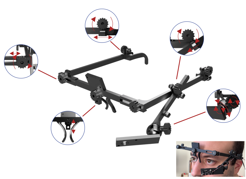
The hardware is centered on a 3D-printed wearable frame that can support one or more camera modules while allowing positional adjustment relative to the eye. The design emphasizes reproducibility, low cost, and practical adaptability across different users and experimental contexts.
The frame includes support elements for the front structure, nose positioning, side arms, and camera mounting. Depending on the intended use, the system can be assembled in simpler or more extended configurations, ranging from monocular pupil recording to combined eye-facing and world-facing acquisition.
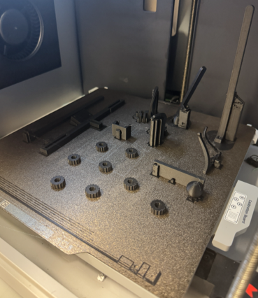
Printing
Assembling
Testing
Bill of materials
List of all components required to build the eyewear platform.
| Preview | Component | Description | Quantity | Notes | Price per Unit(€) | Link |
|---|---|---|---|---|---|---|

|
Printing filament | PLA | 1 | 3D-printed | 1.43 | Open |

|
Eye-facing camera | Primary recording camera | 1 | Required | 7.19-14.38 | Open |
|
|
World-facing camera | Scene camera for gaze mapping | 1 | Optional | 7.19-14.38 | Open |
|
Fasteners | M3 and M2 screws and nuts | Multiple | Required | 1.23 | Open |
|
IR illumination | External LED source | 1 | Depends on the setup | 41.2 | Open |

|
Extension Cables | USB extension cable(s) | 1 | Depends on the setup | 9 | Open |
Filament
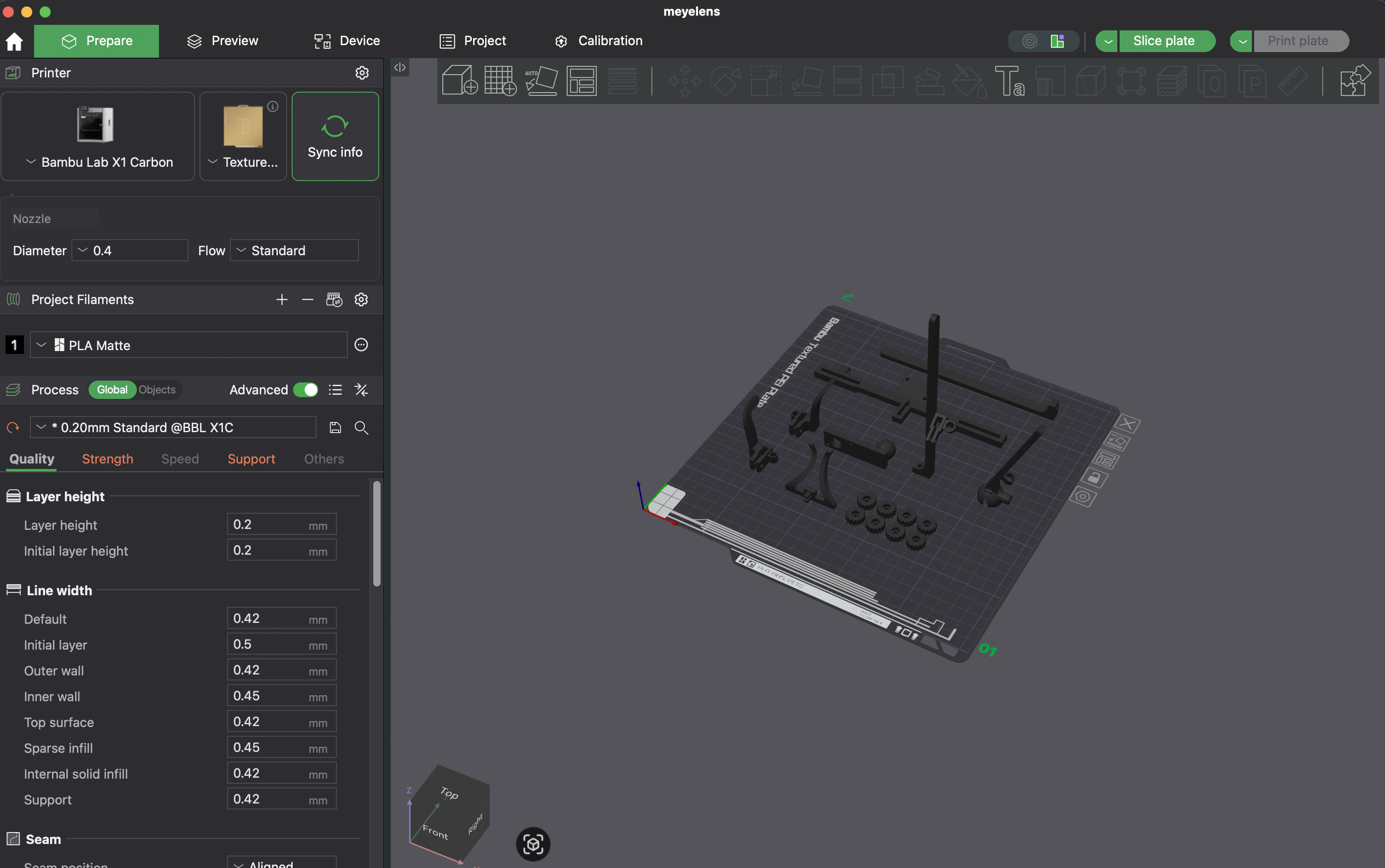
The eyewear frame can be printed with standard 3D-printing filaments, we tested only PLA.
We mostly used Bambu Lab PLA filaments to print the MEYELens eyewear components. In our builds, we used Bambu Lab Matte Black PLA.
Camera(s)
MEYELens can be assembled with one or two camera modules depending on the intended application.
The platform supports:
- Single camera: pupillometry, optionally combined with chin-rest gaze tracking.
- Dual camera: eye-facing and world-facing cameras for naturalistic gaze tracking.
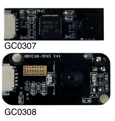
Tested camera modules:
- GC0307 - 640 × 480 px, nominal 30 Hz. The IR-cut filter was removed and the camera was used with an external 96-LED infrared illuminator.
- GC0308 - 640 × 480 px, nominal 30 Hz, with built-in IR LEDs. We used a 50° lens for the eye-facing camera and an 80° lens for the world-facing camera.
Fasteners
Standard fasteners are required to assemble the MEYELens frame and secure the camera module.
Assembly uses mostly standard screws and nuts. Make sure these parts are available before starting the build.
-
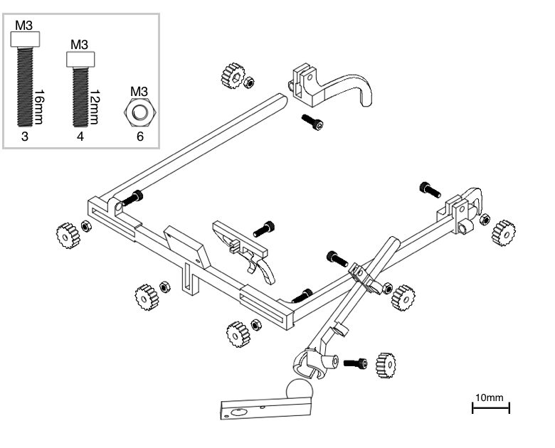
M3 × 16 mm screws ×3
Frame joints. -
M3 × 12 mm screws ×4
Ear supports, camera arm, and ball joint. -
M3 nuts ×6
Used for all M3 screws except the ball-bearing anchor, as in our build. -
M2 × 10 mm screws + M2 nuts
Camera mounting.
Illumination
Infrared illumination can be configured in different ways depending on the experimental setup and portability requirements.
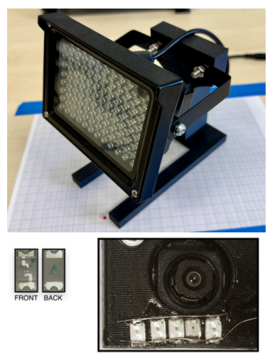
The illumination configuration depends on the camera module and the recording setup. If you use a camera with built-in LEDs, the integrated illumination is sufficient to obtain a good image of the eye. If you use the camera without the built-in LEDs external illumination is required to obtain bright and stable predictions. In this case there are several options:
- External IR light source: the simplest option is to use an external infrared light source. This is easy to set up and can provide strong illumination, but it is less portable.
- SMD LED configuration: a more difficult but portable option is to use small SMD LEDs soldered onto wires and positioned close to the camera lens (4 or 5 should be sufficient).
Extension cable
Camera modules usually require an extension cable for practical use during recordings.
These camera modules have short cables, so a USB extension cable is needed for practical use. If you intend to use only one camera, a common USB extension cable is sufficient. For more flexible setups, we used double-headed USB extension cables such as this USB extension cable. This provides two USB inputs, which can be used either for a dual-camera setup or for one camera together with a custom IR LED array.